|
|
DESIGN OF A MACHINE
PROTOTYPE TO TEST GEARS AND MOTORS |
Sommersemester 2019 osmany.palli@eu4m.eu |
|
|
DESIGN OF A MACHINE
PROTOTYPE TO TEST GEARS AND MOTORS |
Sommersemester 2019 osmany.palli@eu4m.eu |
|
||||||||||||
|
Currently the industry
uses for research in terms of gears and their applications refers to
test benches type gears, since the results obtained in the
simulations are more related to the behavior of these elements in
their actual operation [53]. Generally the gears that
are tested are standardized gears, although you can study different
types, dimensions, with different surface finishes, materials, heat
treatments, lubricants, load regime, the closest to the actual
behavior they will be subjected to, to evaluate specifically certain
desired service requirements. There are two fundamental
types of power loop in
the gear type test banks:
open power loop and closed power loop; the latter can be electrical
or mechanical, as shown in Figure 2.3.
(a)
(b)
(c) Figure 2.3. Gear test
machine with power loop, a) Open, b) closed power loop, electric, c)
closed power loop, mechanical [8, 53, 54] The first case, (a), is
very simple, consists of an actuator coupled to the gears under
study and a brake, which simulates the load. The second case, (b),
an electric motor is coupled to
the input shaft of the gearbox, the output shaft of the box is
connected to a generator that feeds back energy to the system. In
the third case, (c), an electric motor is coupled to the input shaft
of the gearbox and this to the output of another gearbox that have
the same transmission ratio and both boxes are connected to each
other
by axes intermediate, forming a
closed loop. To apply the load
connects a system that can be included in said loop, this mechanism
can be a lever system with weight or hydraulic. This disposition is
known as: circulating power, in English it is known as Four-Square.
Table 2.1.
Advantages and disadvantages of the three types of test benches.
When
designing a test bench, the above must be taken into account, since,
depending on the needs or requirements of the client, the designer
can use previous knowledge to improve or innovate the product.
The Four-Square machine configuration or
circulating power described above, has been widely used in industry
and in the field of tribological research because the results
obtained in the simulations
are quite like reality.
There are many patents over the years.
All these machines, although of different configurations and design
present the common characteristics of the system of
circulating power that are: generator of torque, elements of union
and transmitter of torque. Torque generators are
generally electric motors, but they can also be hydraulic systems.
The elements of union are the systems that transmit the pair from
one system to another and can be axes, couplings and so on. The
torque transmitters are the gear boxes, both test and auxiliary,
that is, they are the elements that transmit torque from one torsion
chain to another. Now, there are several systems or mechanisms to
apply the load to the gears tested. Many of the designs
employ a simple coaxial planetary reducer where torque is applied to
the planetary system by an auxiliary auger transmission mechanism
during the study, such as Lanahan, Klinger, Langenbeck and Basedow.
This mechanism can be operated manually or controlled numerically by
a motor. The test torque is calculated by the difference in the
direction of rotation and the relationship between the sun and the
internal gear. This system has the disadvantage that the applied
torque cannot be controlled. It is necessary to use an additional
system to vary the torque during its execution during testing
without having to interrupt it [55-58]. In other systems the test
torque is applied using two simple coaxial planetary gearboxes
connected by satellites, where the input and output shafts rotate in
the same direction and the gear teeth numbers are calculated so that
the output shaft has an angular velocity deferent to that of the
entrance. The problem with this machine is that you cannot determine
the power losses of the planetary gearboxes. Another design consisted
in connecting another mechanism of two simple coaxial planetary
gearboxes connected by satellites that could be identical to the
previous one as compensation mechanism, to try to overcome the
disadvantage of the machines previously described, but this system
causes additional losses and was more difficult to obtain the power
losses of a reducer [59]. Other designers such as
Musser and Schröder replaced planetary gear trains with harmonic
gearboxes, where it belongs to the group of waveform reducers. The
diameter of the flexible sheet is slightly smaller than that of the
circular flange since it has two teeth less in its outer
circumference. The flexible sheet adopts the elliptical shape
of the wave generator and its teeth conform to those of the circular
flange through the major axis of the ellipse. As soon as the wave
generator begins to rotate in a clockwise direction, the toothed
area of adjustment moves solidly to the major axis of the ellipse.
When the wave generator rotates 180
degrees clockwise the Flexible
Sheet returns with a less tooth position relative to the Circular
Flange. Each complete 360 degree turn of the Wave Generator the
Flexible Sheet moves, counterclockwise, 2 teeth less in
relation to the Circular Flange, thus obtaining the test torque as
shown in Figure 2.4.
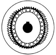
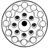
Figure 2.4. Detail of
the interior of a harmonic reducer [60]. The main disadvantage of
this mechanism is that the power losses of the auxiliary motor are
unknown, and it is difficult to
determine the efficiency of the gears under test. Another similar
design by Brüggemann, replaced the harmonic reducer with a cycloidal
reducer, thus increasing the torque values. But the radial component
only transmits stress to the wheel, internal bolts and eccentric
bearings. The cycloidal reducers that have the groove in waveform
instead of a defined
half-moon tend to handle higher
pressure angles. In the case of grooves in wave form, a
greater total force is needed to transmit the same tangential force
that is finally useful in the reducer. This creates a greater radial
force that unnecessarily fatigued the eccentric bearings causing a
rapid wear on these elements, being a disadvantage to take into
consideration [61-63].
Figure 2.5.
Detail of the interior
of a cycloidal reducer [64]. Harald and Yano designed
machines that allow quick change of torque applied to the test gears
by adding additional gears that generate the torque when they are
pulled in the transverse direction, being a mechanically simpler
system. And Bader built a machine based on the same principle, but
the load is applied when one of the boxes of the power loop is
rotated on an axis parallel to the transmission shaft [65-67]. Mihailidis presented a
test bench in which the load is applied by a planetary gear train
previously designed by Wolfrom. Where this mechanism, with the
auxiliary motor included, rotates as a block, and this motor is only
in operation when a load is being applied or it is wanted to be
varied. This system can also use small motors since it has a high
transmission ratio, which allows high test torques to be applied.
One of the advantages that the designer achieves with his machine is
that the efficiency in the gears can be obtained by knowing the
torque applied by the main engine. And one of its disadvantages is
that the load of essay cannot
be changed quickly, which would be an inconvenience to
consider at the time of doing
studies where it requires this type of changes [53, 68, 69]. A machine that has been
very successful in the world market was developed at the Technical
University of Munich, Germany, FZG. The applications of this test
bench are several, for example: to determine the capacity of load to
grasping, the behavior of the coefficient of friction with respect
to wear and the formation of micropitting and pitting. Also, to test
various materials using the same type of lubricant, which offers
results that depend only on the characteristics of the gear
material. Lubricants are also tested and how they affect the
micropitting and pitting formation on the flank of the gear tooth.
The mechanism is relatively simple with a circulating power
structure, in which there is a pair of fixed gears closing the
cycle, and the gears under study, both pairs of gears with the same
transmission ratio. One of the most trees has a device for measuring
the torque. In the other tree, the test torque is applied by means
of a lever and a counterweight. This principle has also been used in
other machines for the testing of hypoid and helical gears of
crossed axes. The device reaches a rotation speed of up to 2250 rpm,
with a torque of 530 Nm and a contact pressure between the teeth of
2 GPa. In addition, it presents vibration sensors that allow the
detection of severe damage during the test.
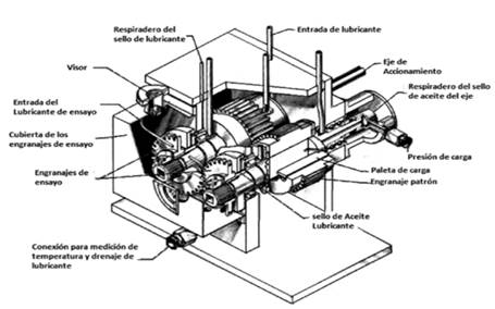
Figure 2.6. Gear Test
Machine FZG [70].
The disadvantages of this
machine are: the upper limit of contact stresses on the geared tooth
is low, the load is static and is changed at relatively high time
intervals [71-88].
Based on the same
principle is the IAE straight tooth cylindrical gear testing
machine. The torque applied to the teeth of the test gears is
applied by a lever
mechanism like that of the FZG
machine. This test bench allows the evaluation of universal and
hypoid transmissions, lubricants and their anti-ripper properties in
the operation since it reaches speeds between 4000 and 6000 rpm, and
the torque between 20 and 407 Nm. The disadvantages are
like that of the
FZG test bench [74, 88-91].
However, depending on the
method with which the load torque is applied, the test machines for
circulating power gears can be classified into mechanical or
hydraulic systems [53]. Many of today's gear test
bench designs apply the test load hydraulically, replacing
mechanically applied load systems. Collins created one of the first
machines applying the test load by means of a hydraulic piston
coupled to one of the axes of the closed power loop, in which a
hydraulic pressure is applied that
generates an axial load on helical flutes that transmit the torque
of testing. This system was designed to operate as a bidirectional
hydraulic piston since the
helical flute mechanism is located on both sides of the hydraulic
piston, but an auxiliary system is
needed to measure the torque that is applied since it becomes very
difficult to control the load with hydraulic pressure. Hennings
created a similar machine that by means of a hydraulic piston
connected to an intoxicating system with helical gears in a drum
generated the load of the test, maintaining the same disadvantages
of the machine previously explained, the variable, friction, affects
the study. However, Schneider based on the same principle designed a
mechanism where friction does not affect the applied load, which
consisted in connecting the cylinders directly from the shaft to the
gear that provides the test torque [91-93]. On the other hand, Ryder,
designed a compact equipment of a single box maintaining the system
Four-Square, where the two pairs of gears have the same ratio of
transmission, two pairs of gears: cylindrical of straight teeth and
the other helical. Its system replaces helical fluted shafts with
helical gears from test benches designed by Collins, Hennings and Schneider.
The test load is applied by supplying a determined oil pressure to a
helical gear and this by an axial movement to the other helical
gear. By controlling
the hydraulic pressure, it is
possible to vary the load accurately during the test. The main
disadvantage is that you
cannot determine the efficiency of
the gear pair under study and
you cannot test gear trains. The
testing capabilities of the machine are very good as it has a high
rotation speed of up to 10,000 rpm and a range of torque applied
between 0 to 270 Nm; which makes the Ryder machine has had
good acceptance in the market and the research of lubricants and
gears tests especially [53, 74, 88, 94, 95]. Shipley on the other hand
creates a mechanism for the application of the test pair consisting
of a drum and inside a rotor equipped with radial fins, where
between the walls of the drum and the fins pressure chambers are
formed, thus generating the torque of trial, by means of oil
pressure in the chambers. This was one of the first test benches to
use pressure chambers for the application of the load and has as
advantages that it minimizes friction and the torque is controlled
by conveniently varying the oil pressure in the chambers. In
addition, it has test torques of up to 8000 Nm. On the other hand,
Kugler created a more compact variant of this system; inside one of
the fixed gears of the Four-Square system designed a hydraulic
rotary cylinder where the pressure chambers are located [96, 97]. The NASA test bench
developed by this same company in the United States of America. Its
principle of operation is
like the previous described. It
can reach a speed of 10,000 rpm, since it has an engine connected to
a belt drive. In addition, it presents a powerful hydraulic system
that can reach a maximum pressure of 690x104 N / m2
and obtain contact voltages close to the two GPa on the tooth
surface of the gear under test. The hydraulic system transmits the
test load on one of the standard gears, and these are connected to
the gears under study. In the machine, four tests are performed for
each pair of gears since the gears are tested with an axial
displacement with which the desired contact voltages are reached,
with a lower torque [54, 98].
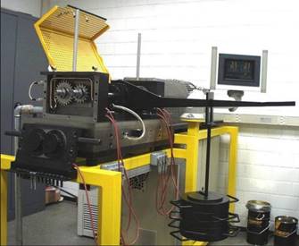
Figure 2.7. NASA Gear
Test Machine [54]
Benches of tests also used to evaluate
bending fatigue in the gears are the machines of circulating power,
which have a configuration mechanically like the machine of Ryder
gear tests. The tests are designed for a certain number of cycles at
speeds below 1000 rpm, with specific loads for the type of study
that you want to perform, which requires controlling all possible
variables that may affect or
falsify the results, that is to
say that product to external or internal factors, occur during the
test the appearance of another type of failure such as wear, contact
fatigue, seizure or other, which were not foreseen in the previous
design of the trial. The main disadvantage of this type of mechanism
is precisely the appearance of another failure before the number of
cycles required for the running test is met. Although if the
programmed testing is completed without being affected by another
factor, the results obtained are accurate [99, 100].
The systems of circulating power or
Four-Square are a mechanical configuration, used basically in the
fatigue test of components [101].
Another interesting test bench is the
push-button type, it is a universal electrohydraulic machine,
controlled by servomotors. This machine is designed for cylindrical
gears with straight teeth, in which several teeth are removed so
that the tool that applies the test load has better access to them.
The test load in these equipment is between 45 and 90 kN and is
applied
through a rod that comes into contact on the flank
of a tooth and the reaction is supported through another rod
that is in the same direction, but in the opposite direction in
contact with another tooth of the gear on the opposite flank since
the gear is placed in a device rigidly supported on an axis, so that
a tooth can be subjected to the study as shown in figure 2.8.
Figure 2.8.
Push-button gear test
bench [102].
The teeth of the gear are tested
independently, in which the test load is applied on a single point
on the tooth. This apparatus is generally used to test the gearing
to fatigue failure by bending at a relatively low economic cost. The
advantages of this equipment are that you can measure the bending
stress at the root of the tooth while the test is running, the
machine automatically stops when the tooth fails, and there are no
variables
such as tree wear, bearings,
deviations in the line of passage of the gears, the gap between
teeth, the errors in the construction of the profile of the tooth,
among other variables that tend to distort the study that is carried
out. The main disadvantages are only trials to cylindrical gears of
straight teeth, the contact is a single point of the tooth by which
few types of faults are tested that affect the gears and are not
recreated in the test the actual operating conditions of the gear
[99, 102-104].
Other designs such as that of Guille Abreu [8] or Pedro Nel Martínez
[54] use designs similar to those previously explained, adding
methodological and / or economic concepts, continuously improving
the equipment with new components, materials and innovations.
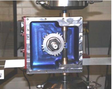
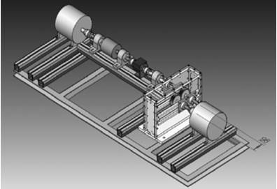
Figure 2.9. Gear test
bench proposed by Martínez [54].
The figure shows a simple, economical and
functional design.
The more complex a system, the more chances of failure.
|
| Mit Unterstützung von Prof. J. Walter | Sommersemester 2019 |