An iterative design process has been chosen to develop the whole
system. At the beginning, the first goal is to obtain raw weight and
accelerometer sensor data from two crutches as fast as possible.
This data will then be analized for feasability and to develop
algorithms to detect and accurately calculate the critical limb load
while walking:
 Figure 3.9.1: General concept of the intelligent crutch.
Develpment will take part in the following two parts:
1.
Test setup with reduced functionality:
Equip two crutches simple and fast with microcontrollers, weight
sensors, accelerometers and batteries in form of breakout boards.
Synchronize measurements by pounding both crutches together and
searching for a peak in acceleration data. Send raw sensor data from
both crutches to android device. Show synchronized data from both
crutches and export it into one .csv-file for further analysis.
2. Fully functional
prototype:
Construct a
fully functional prototype with direct feedback for patient and GUI
for medical personnel. Design and fit PCB with electrical
components. Shrink down mechanical design accordingly.
To realize an efficient solution, a normal crutch will be
modified. The original upper part is unchanged. The lower inner tube
will be modified. It will still be possible to adjust the crutch
length in the usual way. The first step of mechanical development is mounting the weight
sensor. This must be done in a way that axial load is transfered
unchanged to the weight sensor while every lateral load is absorbed
by the crutch tube.
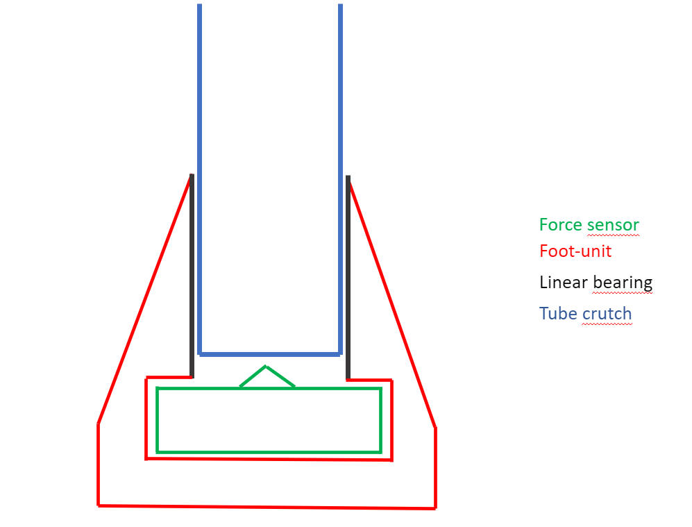 Figure 3.9.2: Design concept of the intelligent crutch.
A first sketch of a possible mounting position of the FX1901
force sensor. The crutch tube is closed at the bottom, so it can
deliver force into the center bump of the force sensor. The main
foot-unit can be 3D-printed in TPU, a high-strength, slightly
flexible material.
Depicted in black is a linear bearing,
possibly an aluminium tube. It takes the side forces, which are
created by the torque of setting the crutch foot on its edge, which
happens in use. It still allows linear movement without significant
friction, so the force sensor can get accurate readings. In the
final design, the opening on top must allow the assembly of the
sensor into the main foot unit.
The following pictures show
CAD design for the test setup. Alle electric components are housed
inside a 3D-printed box.
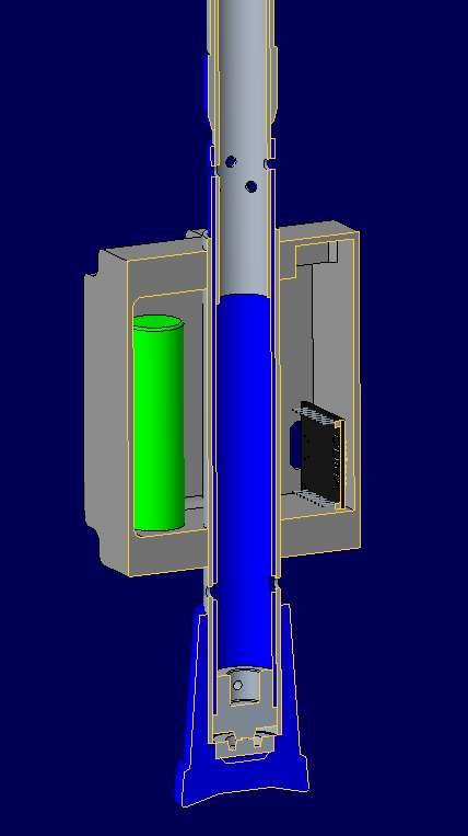
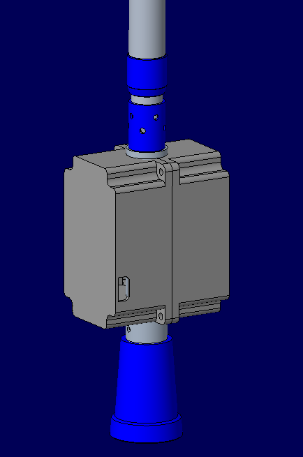
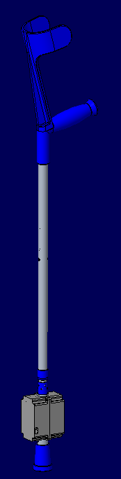 Figure 3.9.3: Mechanical Design of the intelligent crutch.
Electrical components will be integrated inside crutch
tubing for the final prototype:
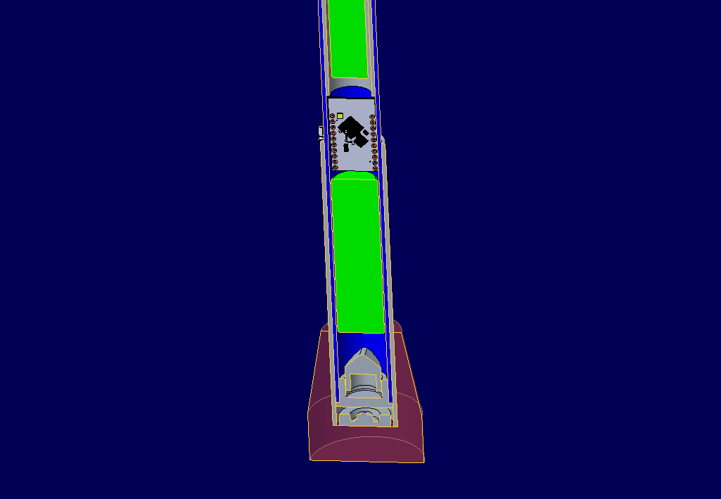 Figure 3.9.4: Electrical components integration