The original inner 19 mm crutch tube is cut and extended by riveting
a 22 mm aluminium tube onto it. This is done to provide more space
inside the tube for accomodation of the electronic PCB in the final
prototype. The 22 mm is closed on the bottom by a 3D-printed cap,
made from PLA (polylactic acid). This part will be made from metal
on a turning lathe for the final prototype.
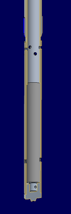
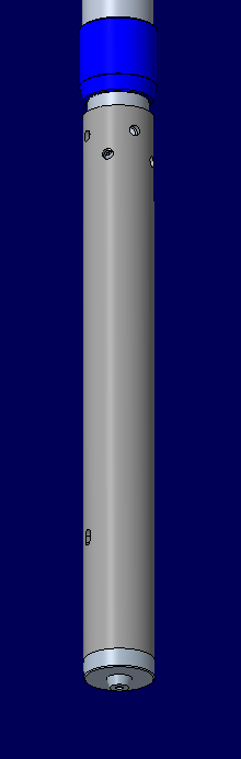
Figure 4.8.1: CAD-Model of the linear bearing and lower assembly
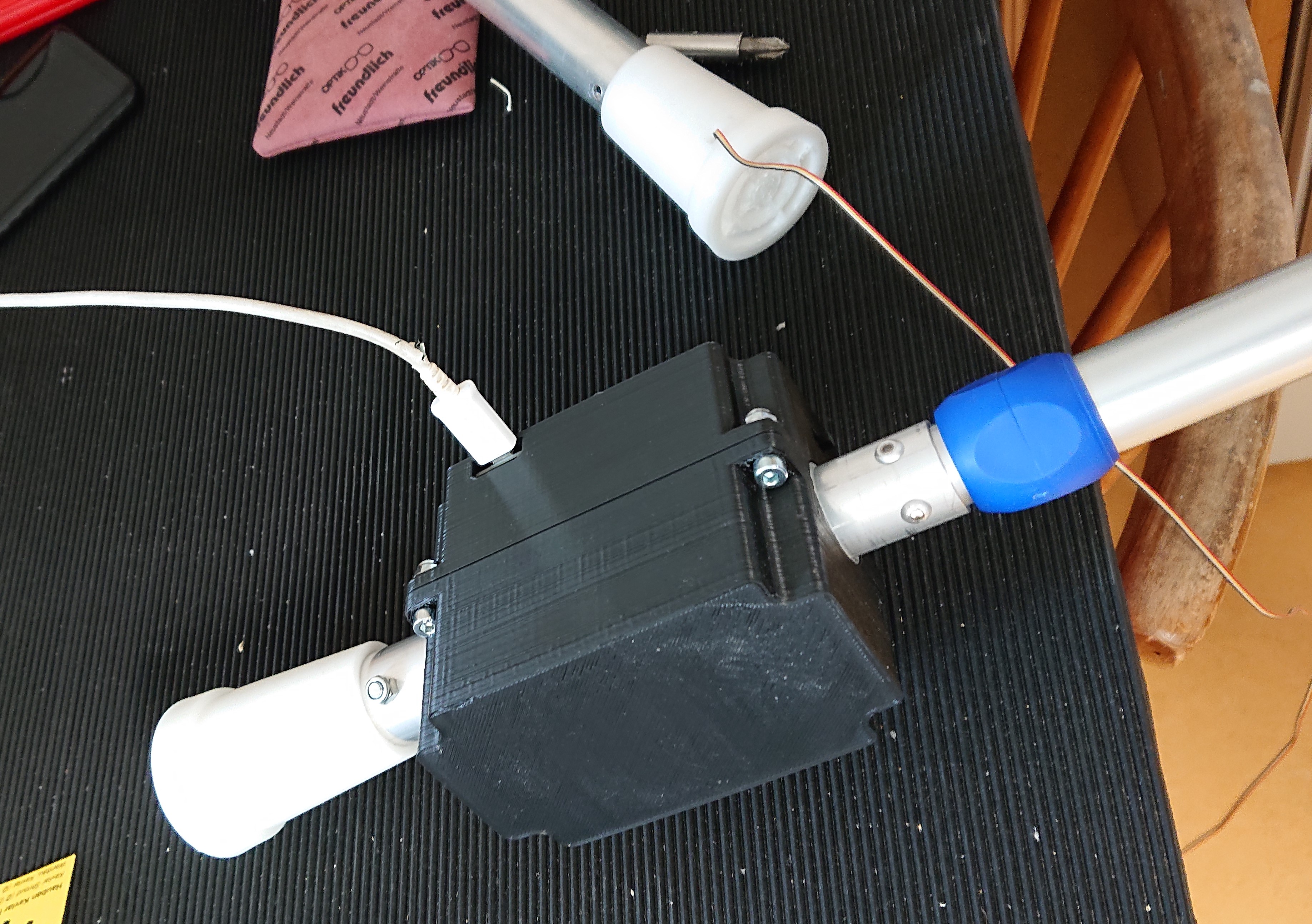
The 22 mm tube serves as one half of a linear bearing. The other
moving half is made from another anodized aluminium tube with 25 mm
outside diameter. Mounted on this tube is a 3D-printed foot made
from TPU (thermoplastic polyurethane), a flexible type of plastic.
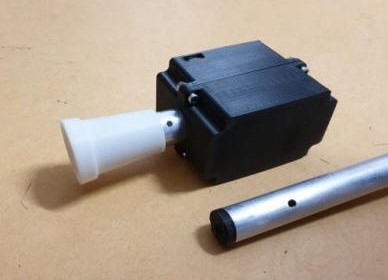
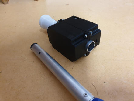
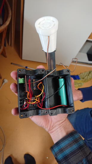
In case of the test setup a 3D-printed box is mounted as well on
this tube to house all electronics. A small opening on the side
gives acccess to a USB micro port for charging the lithium battery
and programming the ESP32 microcontroller. Both subassemblies are
attached via one bolt. This one sits in a circular whole on the
outer tube but in an elongated whole on the inner tube. This allows
for axial movement of a few mm.